NOTE: Only act upon this if you have experience with high voltages.
Here is a practical way to (maybe) see QI thrust at home. I've been musing about using Unruh radiation and QI for thrust for 17 years in my theoretical papers (McCulloch, 2008, 2013) but the capacitor method was proposed by Frank Becker and Ankur Bhatt (2018) and has since been improved by several people, many of whom wish to remain anonymous, but they especially include my post-doc & my research assistant Richard Arundal. Here I describe the thruster we are testing at Plymouth University.
1. The QI Sail / Horizon Drive. A capacitor should be built consisting of a dielectric layer 10-20 micron thick made of kapton (or Krapton as Richard calls it - very fiddly to handle) or polyethylene, and 6x6 cm in area. This is sandwiched between two 4x4 cm aluminium foil plates, finely sanded in their inward facing sides to make sharp 'peaks' to encourage the field emission of electrons. Copper plates, of about 2x2cm are added outside these plates in electrical contact, and power wires are soldered to these copper plates.
2. The power supply can be a 12V battery, but converted up to, 1kV, by a DC to DC converter. There are many other methods. The power is applied to the capacitor. Take care. In our case we slowly ramp up the voltage over 20 minutes, and then slowly discharge the capacitor at the end. The important thing is to have a potential difference between the plates of about 1-2kV, and make sure the dielectric reduces the current across itself to a so-called leakage current on the order of a microAmp. This ensures that the electrons are 'jumping' across at a very high acceleration and therefore see Unruh waves short enough to interact with and be damped asymmetrically by the metal plates. The plates damp the Unruh waves causing a gradient in the field that causes a push (McCulloch, 2021).
3. Place the setup on a balance capable of measuring to 0.01g. Ideally the setup should be self-contained, but this is hard to do. We hope to see forces too large to be explained by interactions between the current & the Earth's magnetic field, for example. These other effects can be calculated anyway.
4. You may want to use a vacuum bag, evacuated of air, around the capacitor to reduce the chance of air pockets in the gaps, which can cause tiny explosions (you see little <1mm punctures in the foil and hear a popping). Also, try to make sure the desk you use is stable (leaning on it can cause a reading) and there are a minimum of conductors nearby. Place a shield around the setup to reduce air flow.
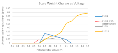
5. Switch on, ramp up the power, watch the balance. If the capacitor anode is facing up, you may see a force down, an increase in weight, since the copper plate below the capacitor is damping the Unruh field below and the drive will move down towards the damped part of the vacuum, or the horizon (which is the copper plate). In our 22 tests so far 14% of them have shown a thrust. See plot below. The rest showed no thrust, suggesting that electrostatics is not a problem). For a theoretical explanation of what is happening, see McCulloch (2021). The QI force you should expect is given by F = 0.00014IA/d^2 where I is the leakage current, A is the plate area and d is the plate separation. For videos of the setup see Arundal (2022) and other videos on his youtube channel.
6. Since I am sharing this information openly, please do the same and tell me about your results. Also, take great care, and it is best if you try this only if you have experience of high voltage. 1kV is not trivial.
7. Enjoy being cutting edge! You are now a Horizoneer.
References
McCulloch, M.E., 2013. Inertia from an asymmetric Casimir effect. EPL, 101, 59001. https://arxiv.org/abs/1302.2775
Becker, F.M. and A.S. Bhatt, 2018. Electrostatic accelerated electrons within symmetric capacitors during field emission condition events exert bidirectional propellant-less thrust. Arxiv: https://arxiv.org/abs/1810.04368
Arundal, R., 2022. Podcast on recent build: https://www.youtube.com/watch?v=sB3pqlHvA_s
McCulloch, M.E., 2021. Thrust from symmetric capacitors. Preprint: https://www.researchgate.net/publication/353481953_Thrust_from_Symmetric_Capacitors_using_Quantised_Inertia